Nonpolarizing electrodes
Nonpolarizing electrodes, sensors, non polarizable electrodes
Ringlo ut 39
Budapest 1221
ph: +36 1 2261870
alt: +36 30 2123517
simandra
The measurements were performed on 2010 November, 2012 January, 2013 Jule, August and 2014 August, September, Oktober.
The objective of the test measurements was not to study the characteristics of single electrodes at „sterile” laboratory conditions. We aimed to reveal the main features of electrode couples at conditions resemble what one meets during everyday use on the field. So we studied the self-potential and electric resistance of the couples, and the long term variation of these quantities assuming a relatively careful use of the electrodes.
In addition we examined the magnitude and decay of the contact (liquid junction) and diffusion effect what occurrs and changes at the contact (junction) between the couple and various ground (solution) when the electrodes were set.
For this reason the electrodes were tested outdoors at different environmental conditions (e.g. ground pit, bentonite block, in salt water) and were subjected to electromagnetic noise, temperature changes and certain effects what arised from the change in the physical parameters of the ground, bentonite, salt water due to temperature changes.
* * *
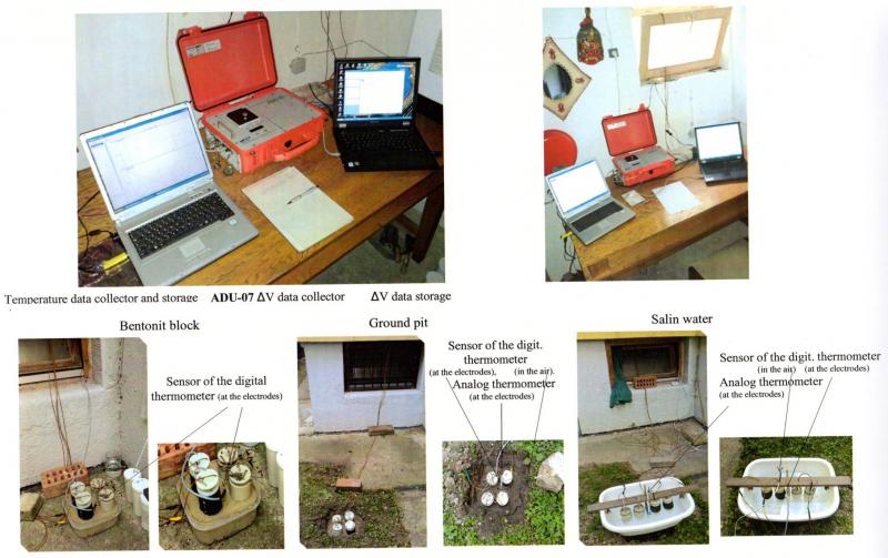
In 2010, 2012 the data collector was an ADU-06 borrowed from Eötvös Lorand Geophysical Institute of Hungary, while in 2013, 2014 the data collector was an ADU-07 from Metronix Geophysics (Braunschweig, Germany).
Please see the larger version of the Figure by klicking the + in the lower right corner what will appear when you draw the cursor to the figure.
Figure 1: The measurement setup. The electrodes (black: conventional long type, grey:long cheramic slab type), from left to right: on a bentonit block, in ground pit, in salt water.
* * *
The self (DC) potential
The full potential (V) that can be measured on a couple of electrodes is usually the sum of the self potential (Vs), the contact (polarization) potential (Vc), and the target potential (Vt) that originates from the soil that is under investigation.
The potential Vs is generated by the interaction between the lead spiral and the PbCl (solid) electrolyte that surrounds it. Consequently its value does not depend on the type of the ground on which the electrode is placed. Over a longer time scale of course this may change (DC dritft), as the solid electrolyte may change next to the lead spiral.
The contact potential Vc forms prompt when the bottom of electrodes comes in contact with the ground but it decays relatively quickly.
Since the electrodes was placed directly next to each other (see Figure 1) thus Vt was virtually zero in this case. After the decay of Vc (see Figure 6, 7, 8, 9) the measured potential thus determines the value of Vs. This is shown as a function of time elapsed from the date of manufacturing (taking the temperature dependence into account as well).
The long time variation of Vs (DC drift)
Please look at the larger version of the Figure by clicking the + in the lower right corner what will appear when you draw the cursor to the figure.
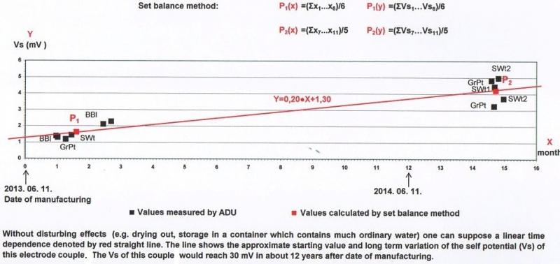
Figure 2: Approximate time variation of self potential (Vs) of the long gypsum type electrode couple, determined from Vs data measured at 20 Co, on bentonite block (BtBl), in ground pit (GrPt) and salt water (SWt).
Conclusion:
This electrode couple can work for 10-12 years if one uses it carefully and keeps the „Direction for use, transport, storage and maintenance of nonpolarizing electrodes; ….” (henceforth User Guide) you can find in Services of this website. The Vs (DC) drift (derived from the slope of the line) of this couple is 0.2 mV/month, thus the stability of Vs (DC) is very good.
Note:
1. In practice the electrodes cannot be used for such a long period of time, due to other processes (e.g. physical wear, degradation of the plaster and PbCl from the bottom of the electrode, corrosion of the wire, or chemical changes in the matrix).
2. This measured result is valid specifically for this electrode couple in case of careful use, storage and maintenance. In case if we used another couple of electrodes we would get a different Vs. So it is important to compile an electrode couple taking two electrodes, self potential of each electrode shall be as close as possible. Thus the Vs of the couple can be minimized.
* * *
Please look at the larger version of the Figure by clicking the + in the lower right corner what will appear when you draw the cursor to the figure.
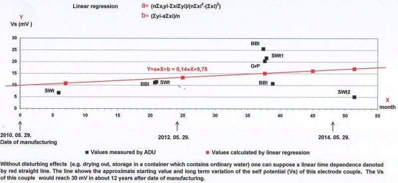
Figure 3: Approximate time variation of self potential (Vs) of the long ceramic slab gypsum type electrode couple, determined from Vs data measured at 20 Co, on bentonite block (BtBl), in ground pit (GrPt) and salt water (SWt).
Conclusion:
This electrode couple can work also for 10-12 years if one uses it carefully and keeps the User Guide you can find in Services of website. The Vs (DC) drift (derived from the slope of the line) of the couple is 0.14 mV/month, thus the stability of Vs (DC) is good.
Note:
1. In practice, this type of electrode neither can be used for such a long time (because of the aforementioned reasons), but its lifetime would be at least 30 to 40% longer than for the type without the ceramic slab since the ceramic slab slows down the dehydration process, or diffusion between the electrode and the ground, which caused the change of Vs.
2. This measured result is valid specifically for this electrode couple in case of careful use, storage and maintenance. In case if we used another couple of electrodes we would get a different Vs. So it is important to compile an electrode couple taking two electrodes, self potential of each electrode shall be as close as possible. Thus the Vs of the couple can be minimized.
* * *
The self (internal) resistance
If the electrodes are placed next to each other (as in Figure 1), then the total resistance measured with the ADU recorder is the sum of the self (internal) resistance of the electrode couple (R) and the contact resistance (Rc) that arises between the bottom of the electrodes and the ground. Rc is usually much smaller than R, so the figures reflect the variation of R with a good approximation. Nevertheless the Rc can increase significantly if the ground dries (especially sandy ground).
The long time variation of self resistance
Please look at the larger version of the Figure by clicking the + in the lower right corner what will appear when you draw the cursor to the figure.
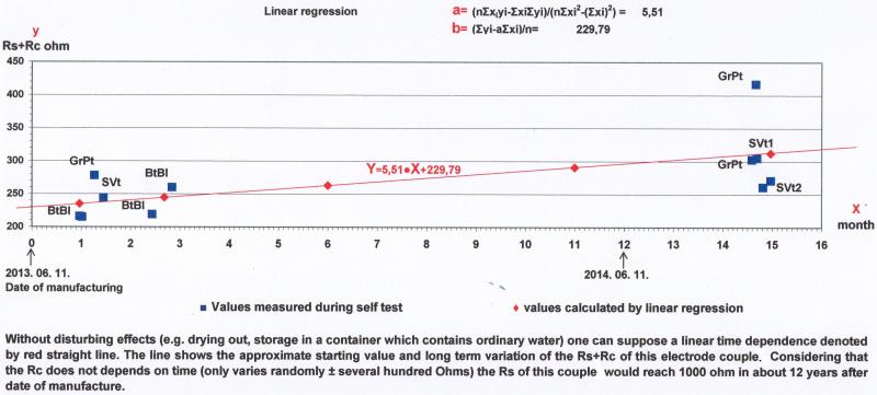
Figure 4: Approximate time variation of self resistance (Rs) of the long gypsum type electrode couple, determined from Rs+Rc data measured on bentonite block (BtBl), in ground pit (GrPt) and salt water (SWt).
Conclusion:
In case of the long electrode couple type the time for the internal resistance to rise up to 1000 Ohms is estimated to be 10-12 years if one uses it carefully and keeps the User Guid. 1000 Ohm or even higher internal resistance is considered to as undesired by some companies that use the electrodes. The increase of Rs (derived from the slope of the line) of the couple is 5.51 ohm/month.
Note:
1. The measured values display relatively large standard deviation (see Figure) because of:
- the moisture content of the electrode couples is able to vary randomly (drying ) and then regenerate (if put back to the container or watered on the ground); which results in the increase and subsequent decrease of R.
- Rc shows similar variations that are seemingly random. Its value increases when the soil dries and decreases when the wetness content regenerates.
2. In practice the electrodes cannot be used for such a long period of time, due to other processes (e.g. physical wear, degradation of the plaster and PbCl from the bottom of the electrode, corrosion of the wire, or chemical changes in the matrix).
3.This measured result is valid specifically for this electrode couple in case of carefull use, storage and mainenance. In case of another couple of electrodes we would get a different numerical values and temporal dependence for R.
* * *
Please look at the larger version of the Figure by clicking the + in the lower right corner what will appear when you draw the cursor to the figure.
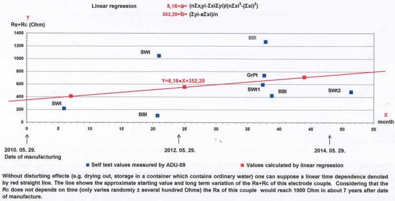
Figure 5: Approximate time variation of self resistance (Rs) of the long ceramic slab gypsum type electrode couple, determined from Rs+Rc data on bentonite block (BtBl), in ground pit (GrPt) and salt water (SWt).
Conclusion:
In case of the long gypsum ceramic slab type of electrode couple the time for the self resistance to rise up to 1000 Ohms is estimated to be 6-7 years, since its initial value is relatively higher because of the ceramic slab. The Vs (DC) drift (derived from the slope of the line) of the couple is 0.14 mV/month, thus the stability of Vs (DC) is good. The increase of Rs (derived from the slope of the line) of the couple is 8.16 ohm/month.
Note:
The true lifetime of the electrodes is smaller because of the reasons described at Figure 3, however thanks to the robustness of the construction it is still larger than for the long type.
* * *
The contact (liquid junction) and diffusion effect
When the electrode couple is placed on the ground (or into another electrolytic media) then a Vc contact (liquid junction) and diffusion potential (hereinafter called the contact potential Vc) forms between the electrode couple and the medium, because of: - there is a difference in the ion (mainly Na+, Cl-) concentrations between the inside of the electrode and the surrounding media and in the mobility of it's ions, so it occurs the liquid junction potential at the contact, - the diffusion of ions (through the contact) continuosly decreases the concentration differences so the liquid junction potential decays to zero with time.
The Vc disappears after a certain amount of time. Our experience: the decay curve can be approximated by an exponential function. The decay time depends both on the type of electrode and the characteristics of the ground or surrounding media.
Please look at the larger version of the Figure by clicking the + in the lower right corner what will appear when you draw the cursor to the figure.
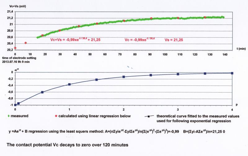
The temperature effect was negligible thanks to it's less than 1 Co change.
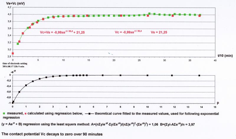
Figure 6: Decay of the contact potential (Vc) of the long gypsum electrode couple on the bentonite block; time variation of the measured, calculated and theoretical data.
Please look at the larger version of the Figure by clicking the + in the lower right corner what will appear when you draw the cursor to the figure.
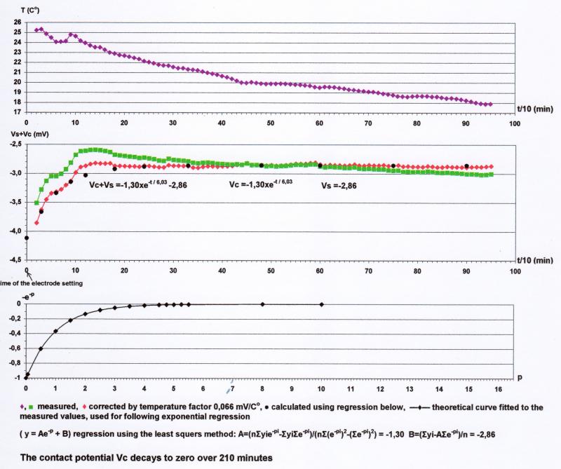
Figure 7: Decay of the contact potential (Vc) of the long gypsum electrode couple in ground pit (grassy garden soil); time variation of the measured, temperature effect corrected, calculated, and theoretical data.
Please look at the larger version of the Figure by clicking the + in the lower right corner what will appear when you draw the cursor to the figure.
The temperature effect was negligible thanks to it's less than 1 Co change.
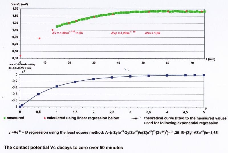
Figure 8: Decay of the contact potential (Vc) of the long gypsum electrode couple in ground pit; time variation of the measured, calculated and theoretical data.
Please look at the larger version of the Figure by clicking the + in the lower right corner what will appear when you draw the cursor to the figure.
The temperature effect was negligible thanks to it's less than 1 Co change.
Figure 9: Decay of the contact potential (Vc) of the long ceramic slab gypsum electrode couple in ground pit; time variation of the measured, calculated and theoretical data.
Conclusion:
The Vc of the couples became less than 0.5-1.0 mV in 10 minutes after setting the electrodes and decays close to zero in 50-120 minutes.
Note:
10 minutes after setting the electrodes the Vc is usually negligible compared to target (MT, SP, IP) signal. If however the target potential is small or comparable to Vc, then it is worth to wait until it decays and to start the recording of data only afterwards. It is advised to verify these relations during a preliminary measurement.
In case of SP research, to avoid the noise from contact diffusion effect, it is advised to carry out the measurements: cover the target area by a network of measuring points using a lot of electrodes, let wait half or one hour and then measure the points successively, using some electronic V switch device.
Nonpolarizing electrodes, sensors, non polarizable electrodes
Ringlo ut 39
Budapest 1221
ph: +36 1 2261870
alt: +36 30 2123517
simandra